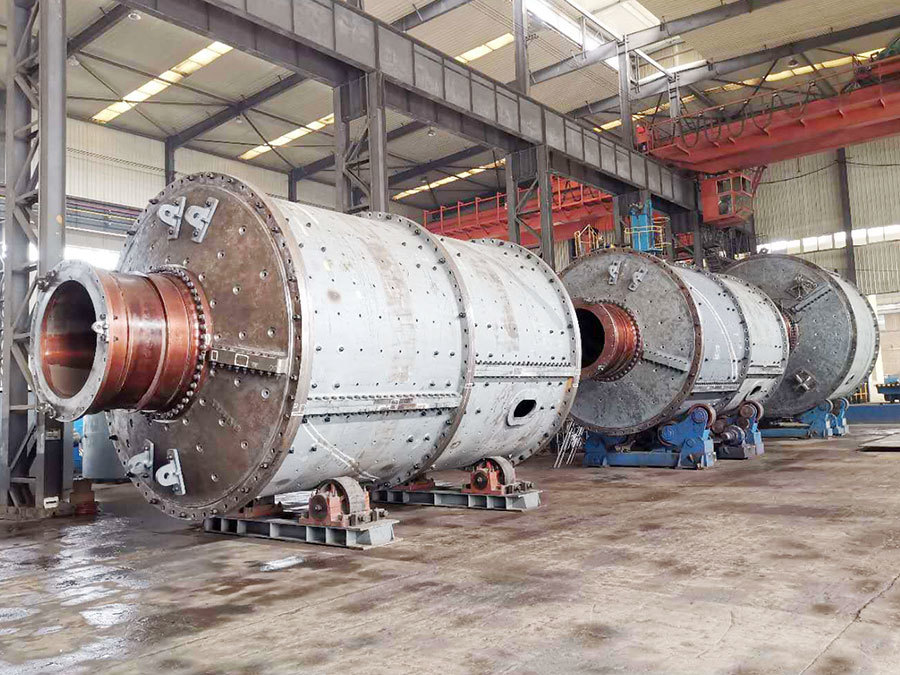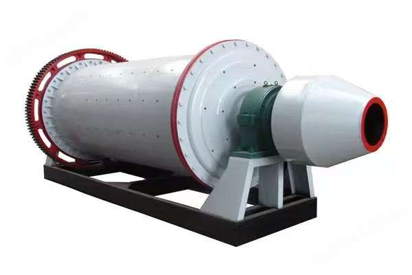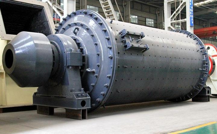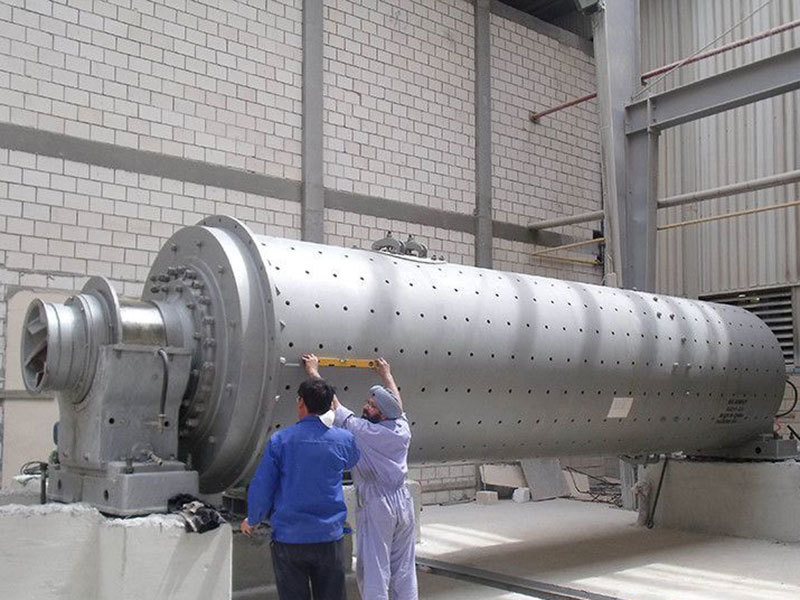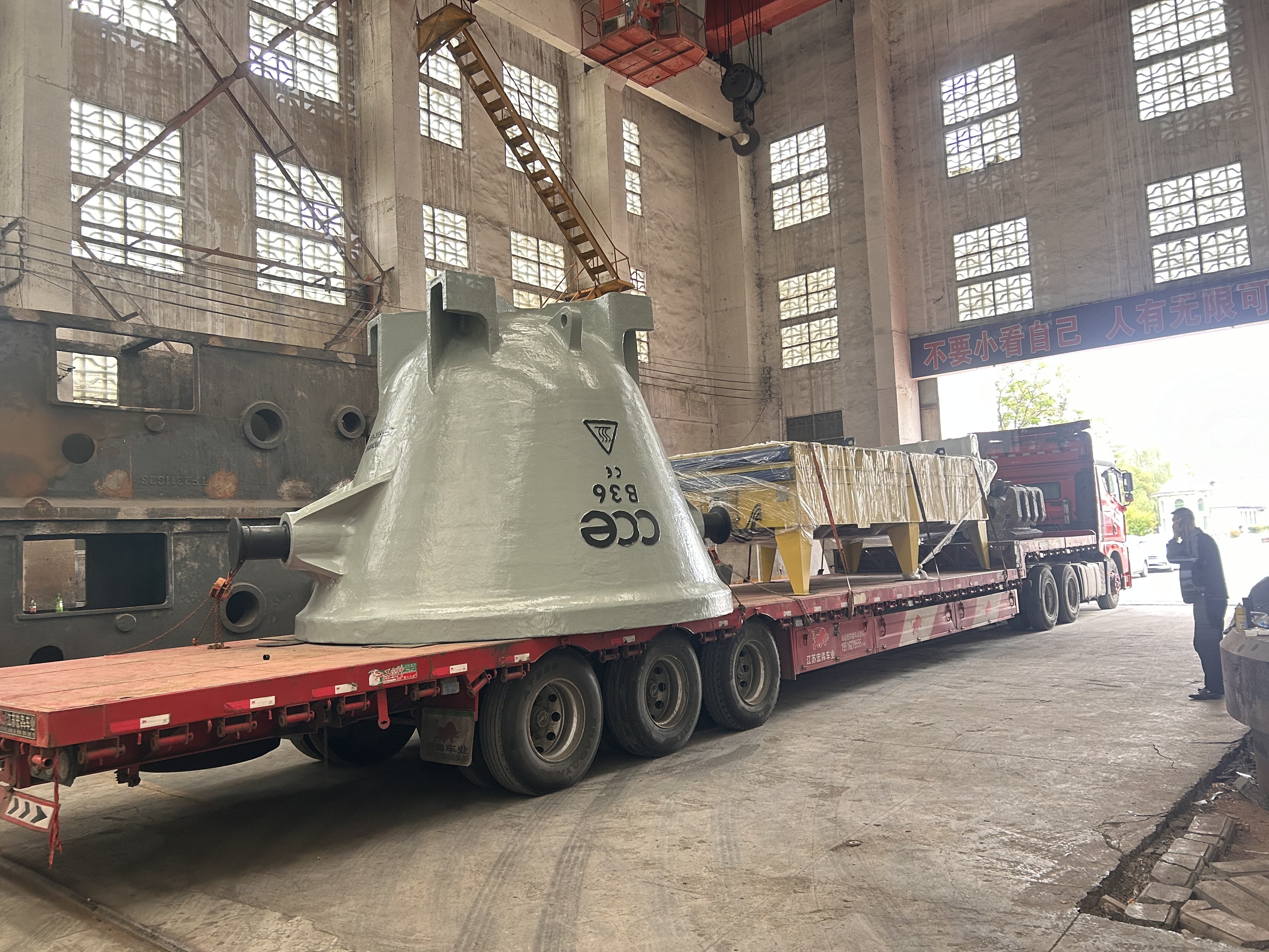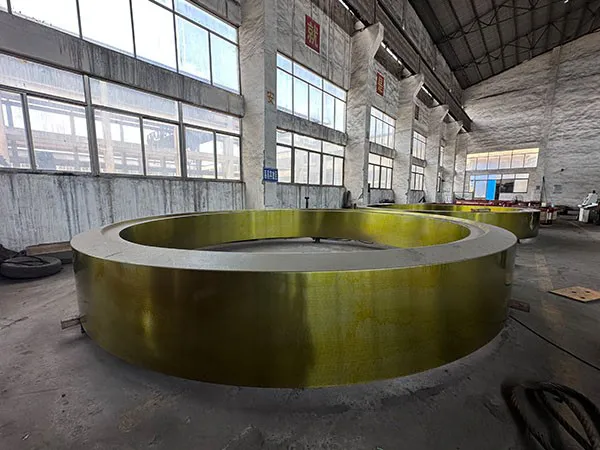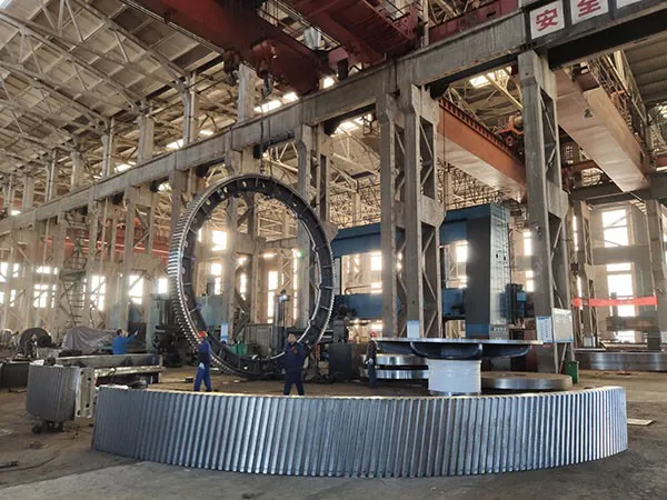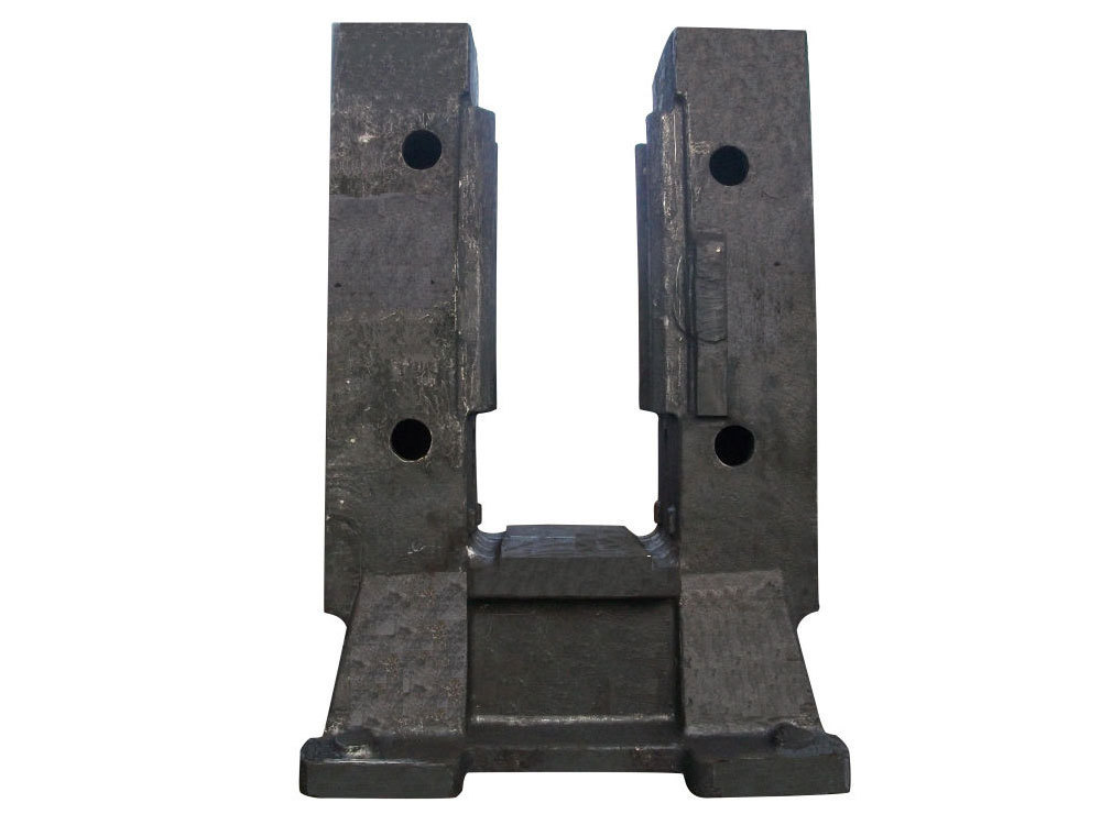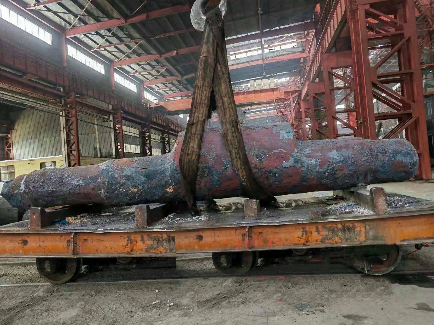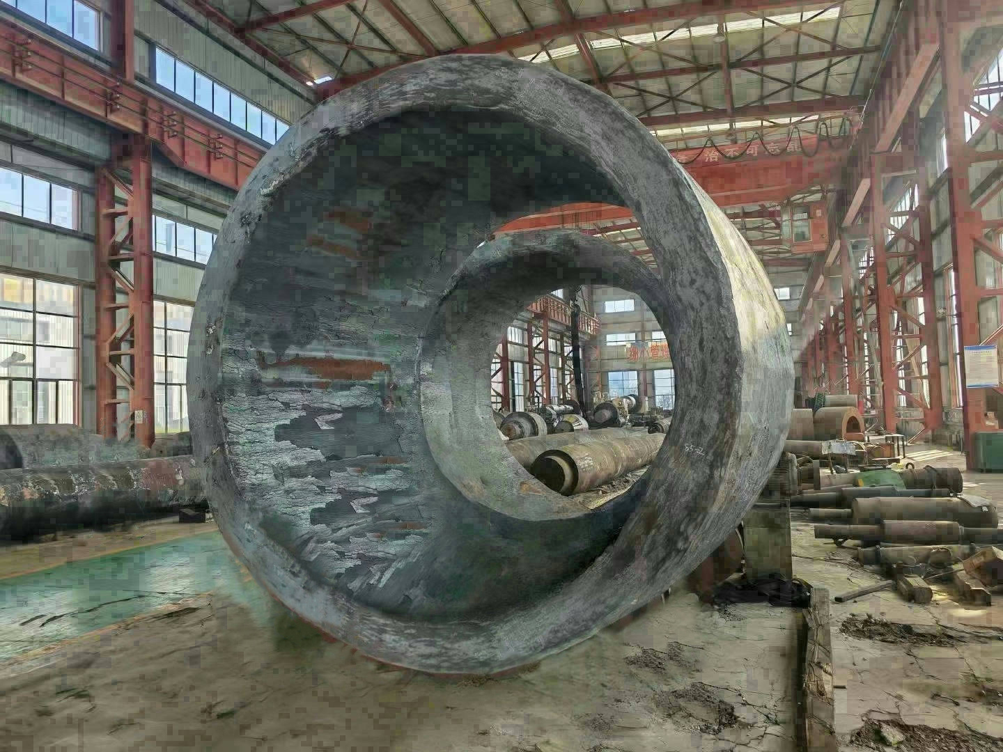


I. Introduction to the Ball Mill Cylinder
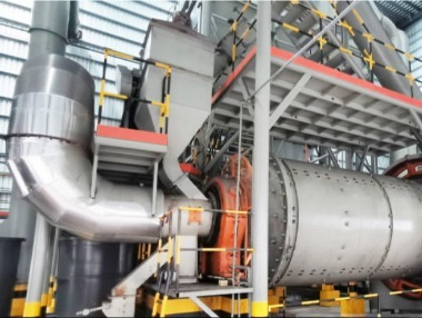
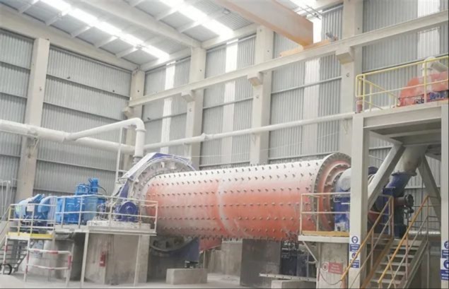
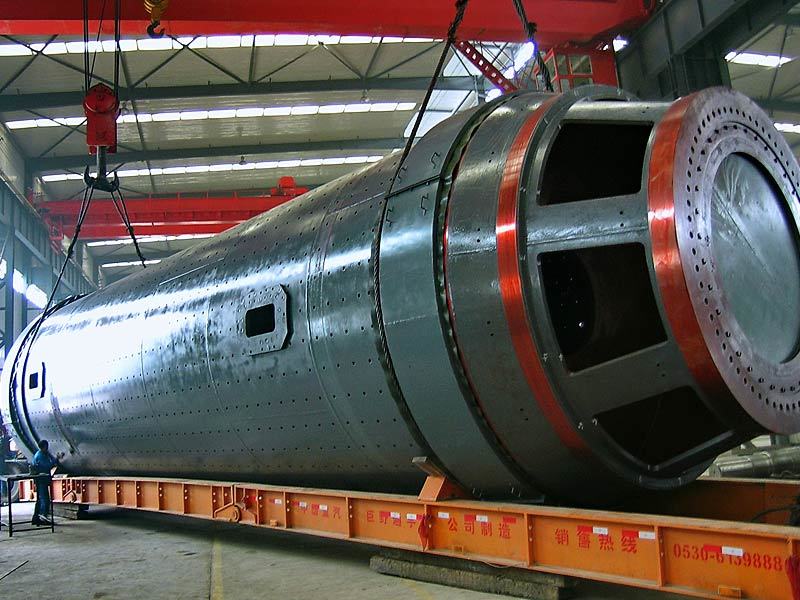
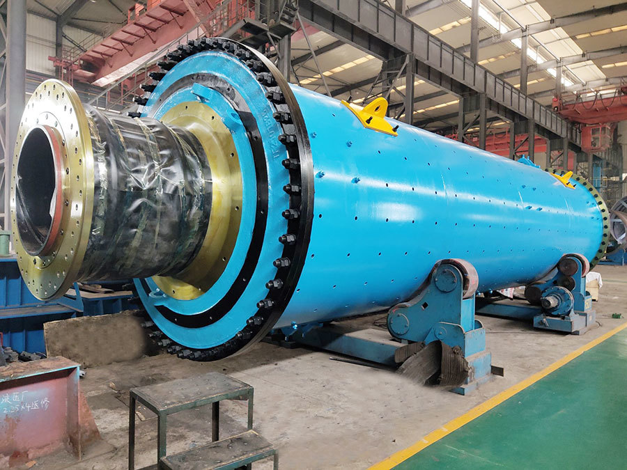
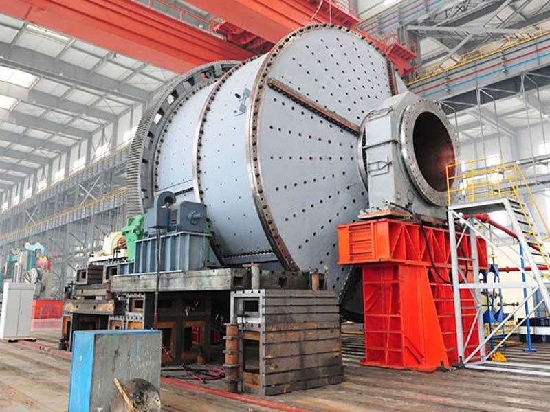
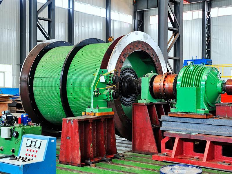
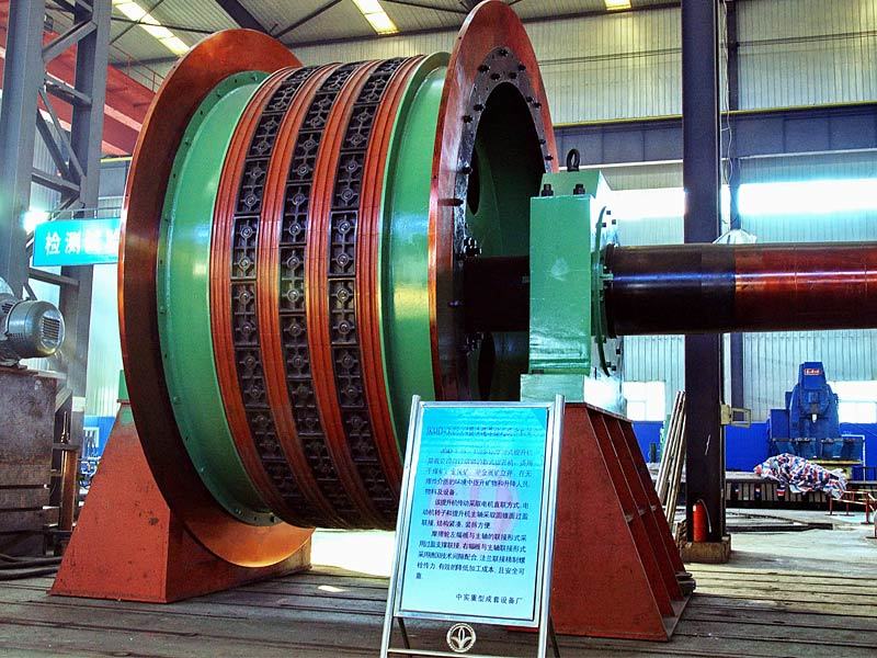
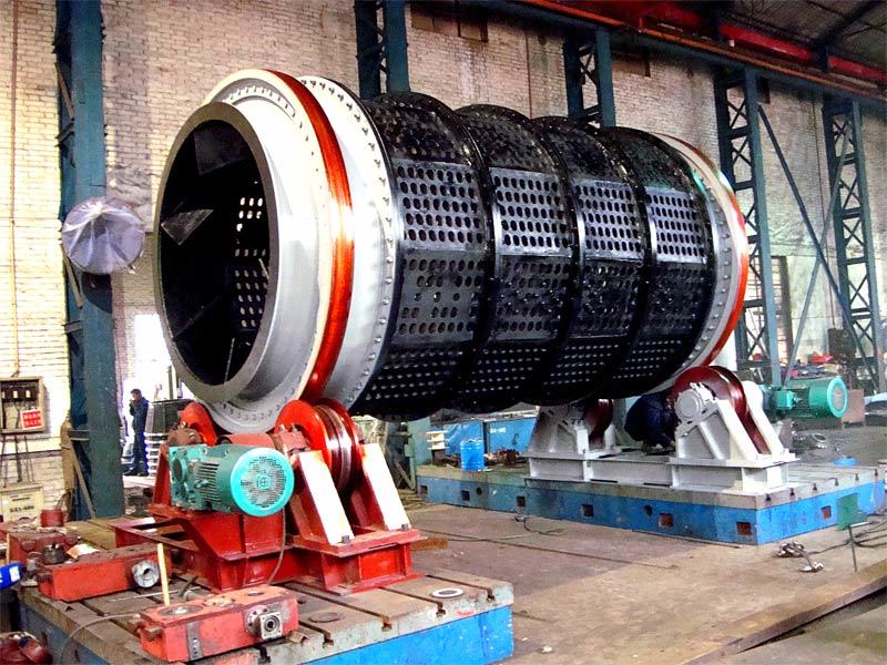
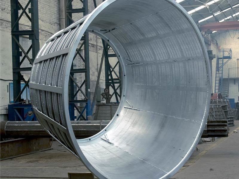
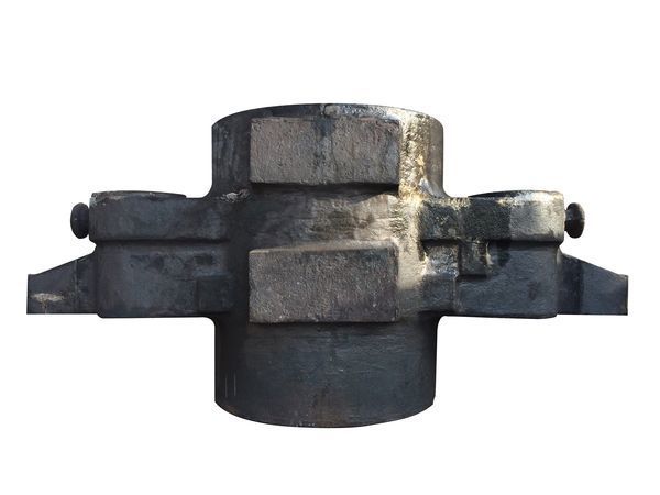
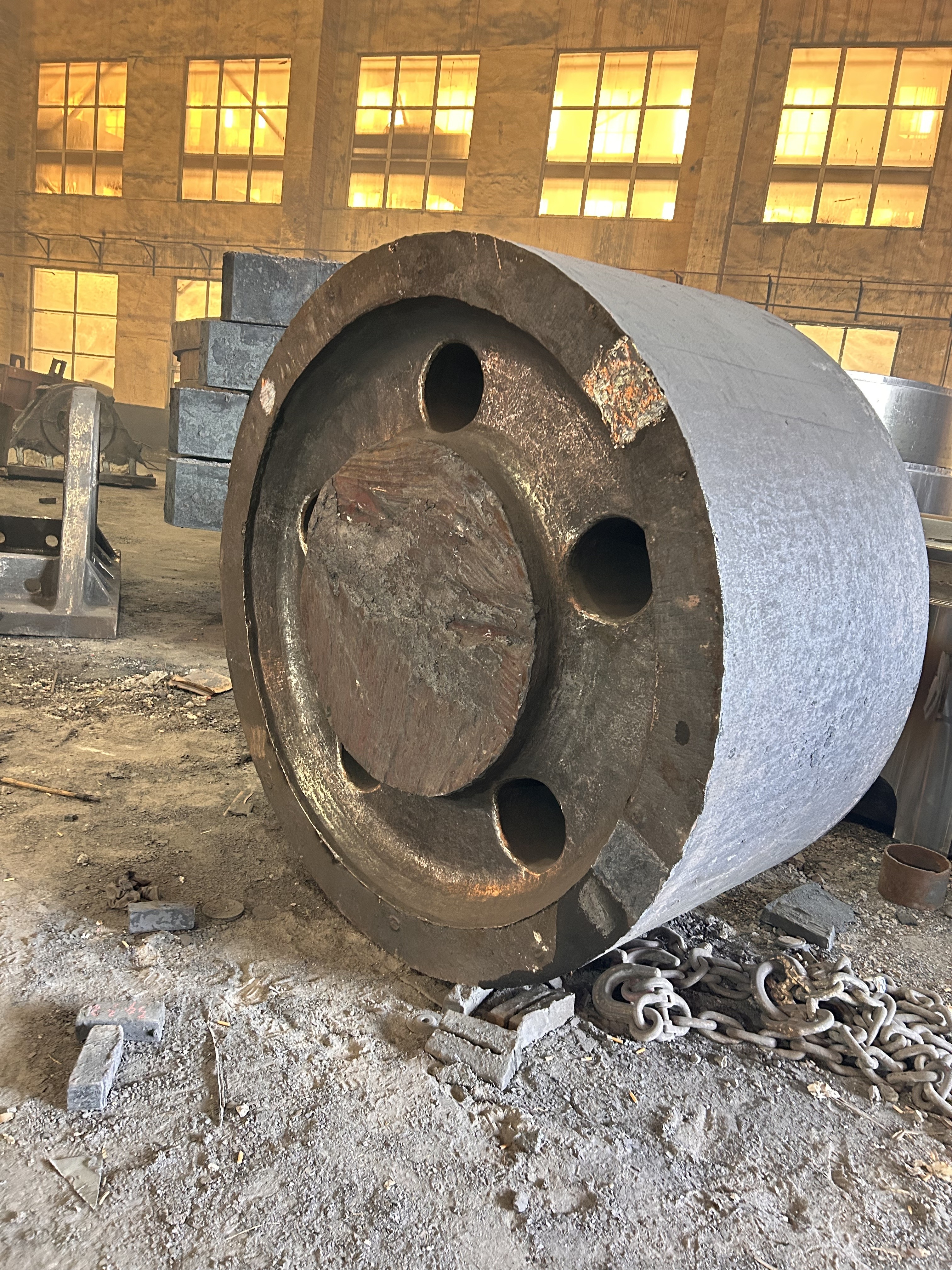
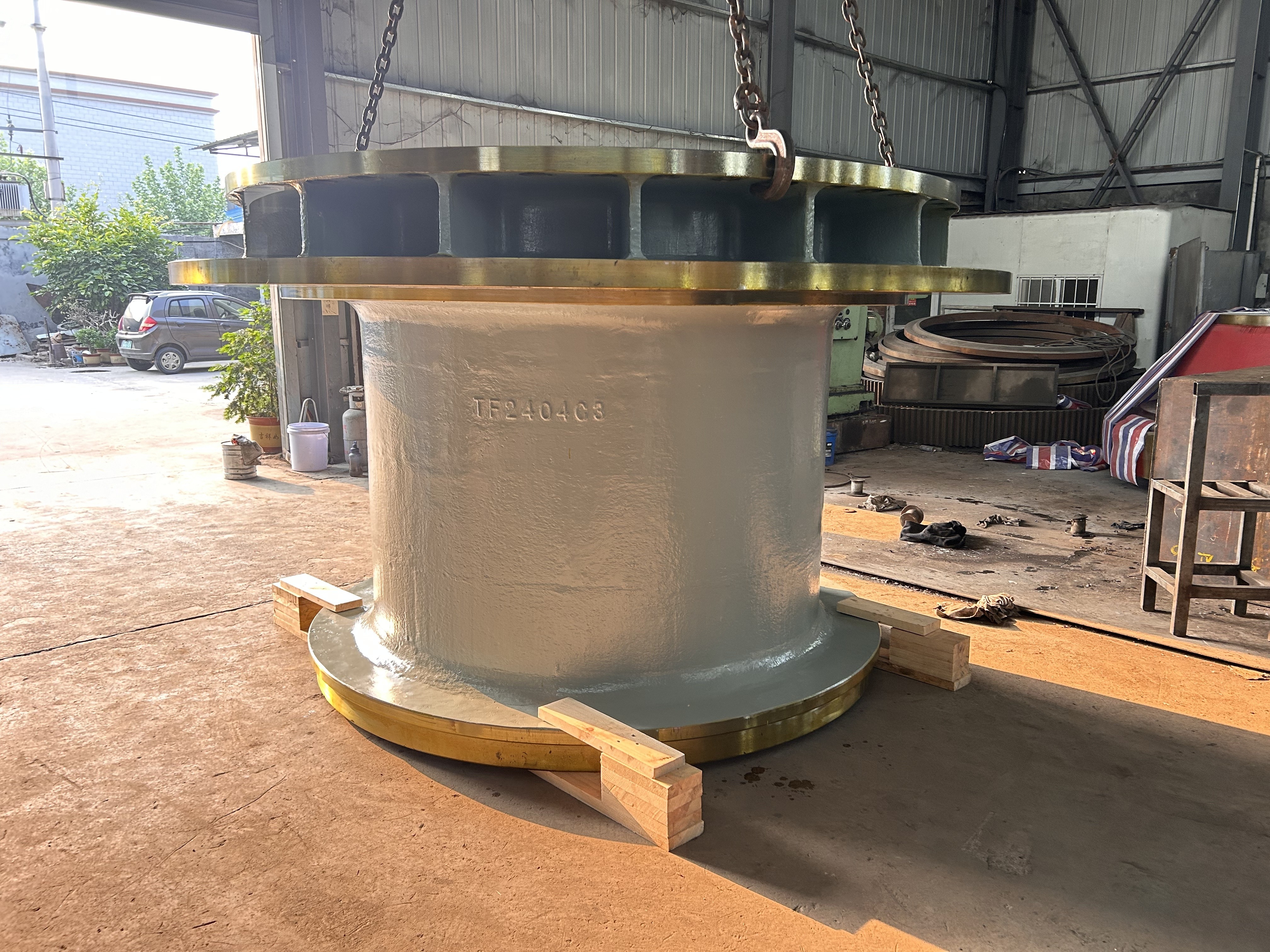
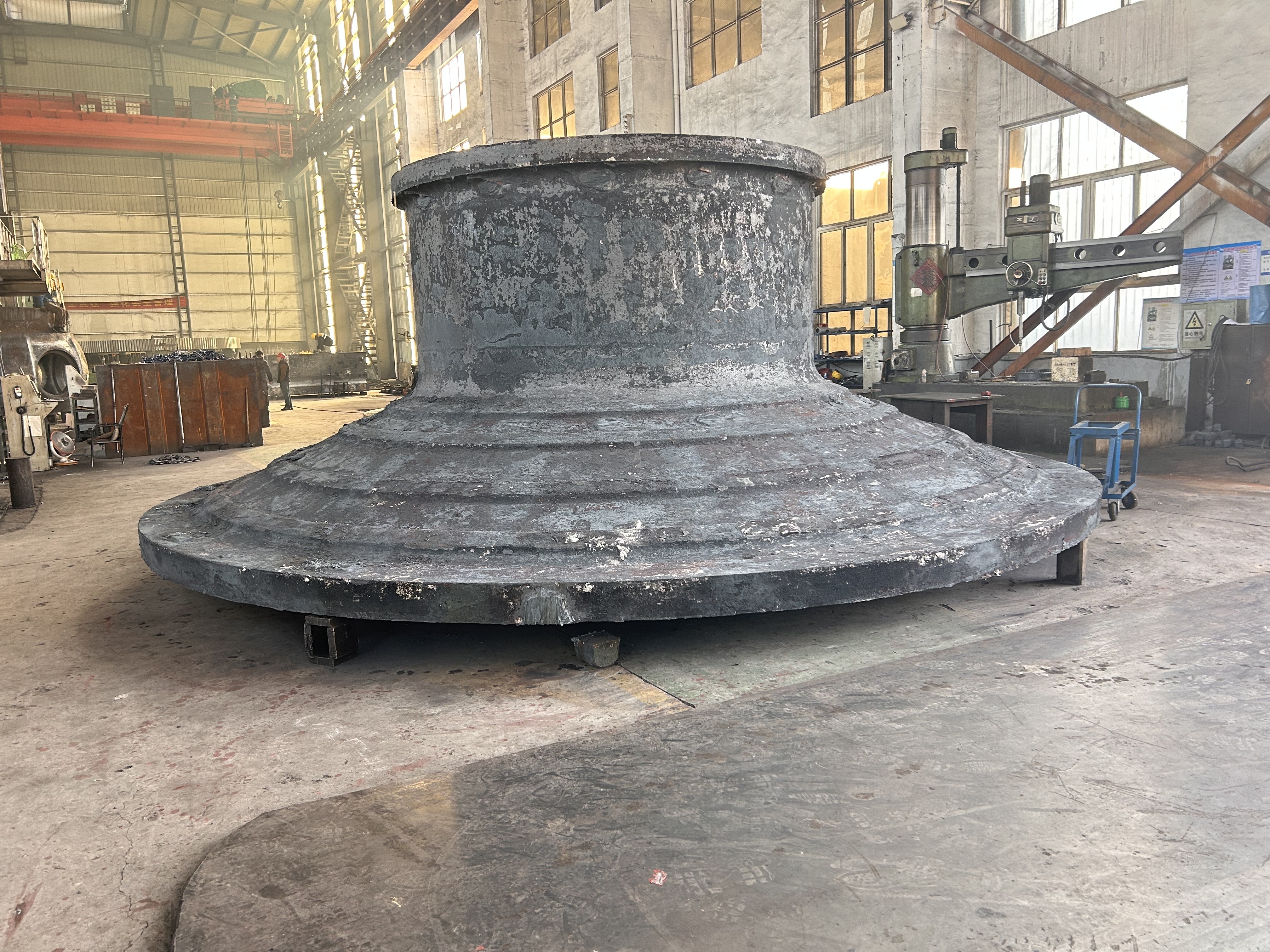
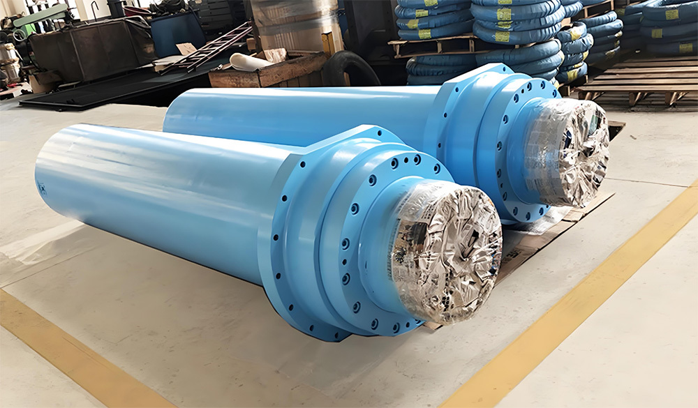
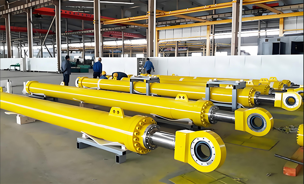
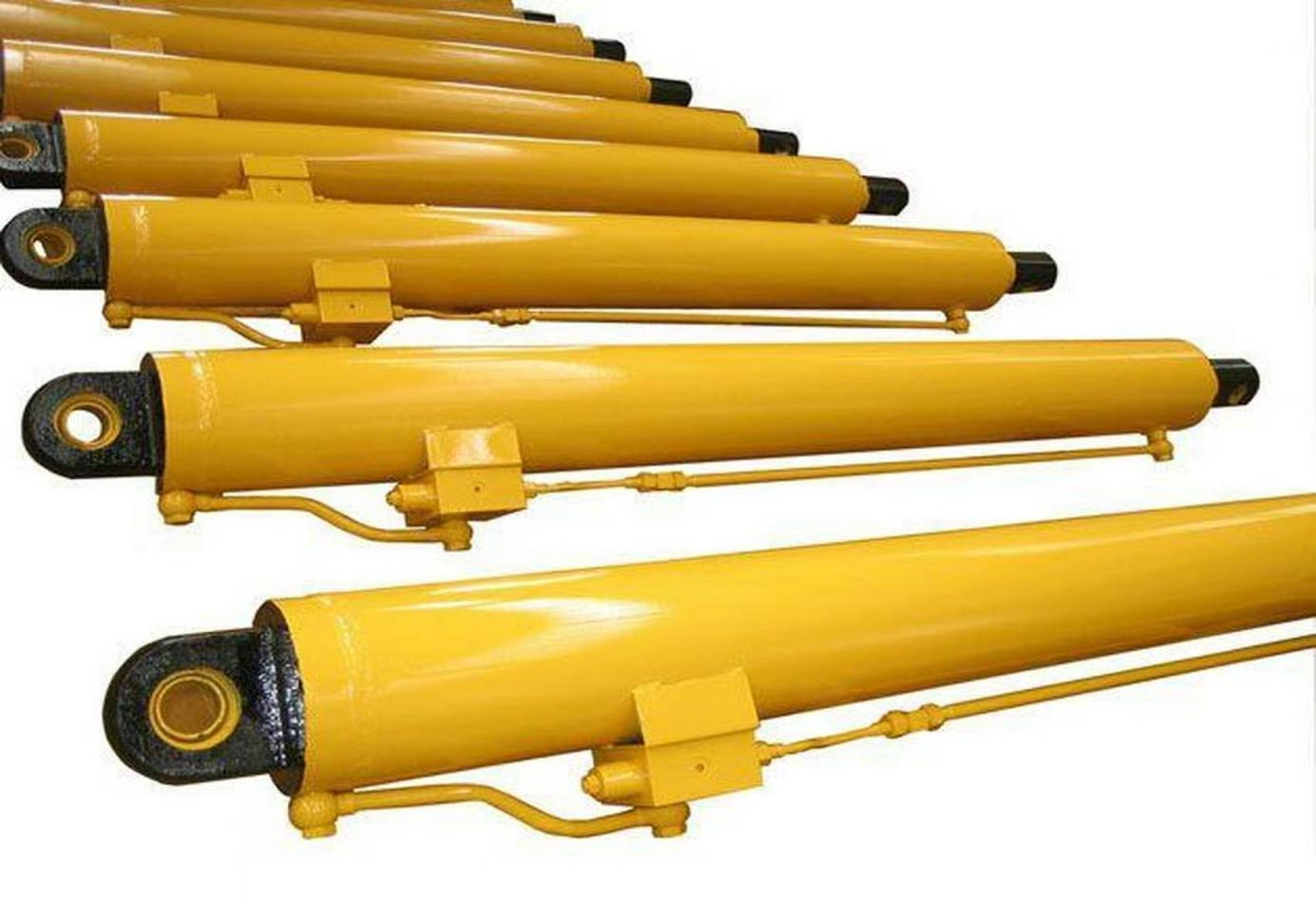
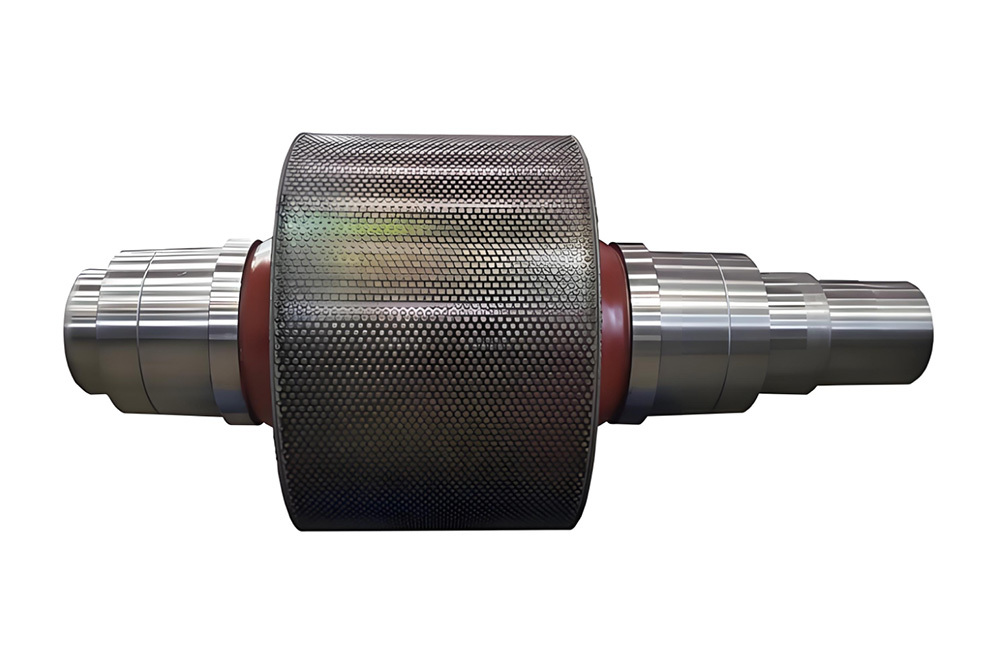
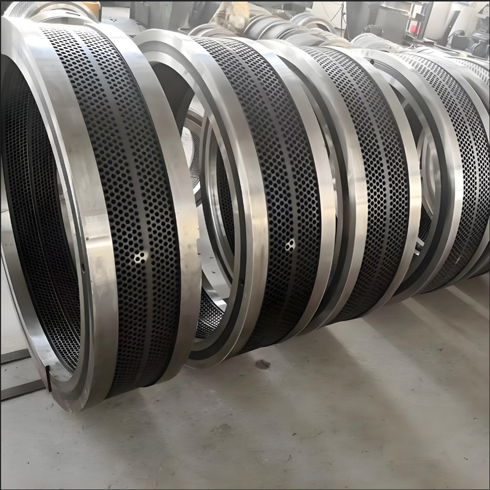
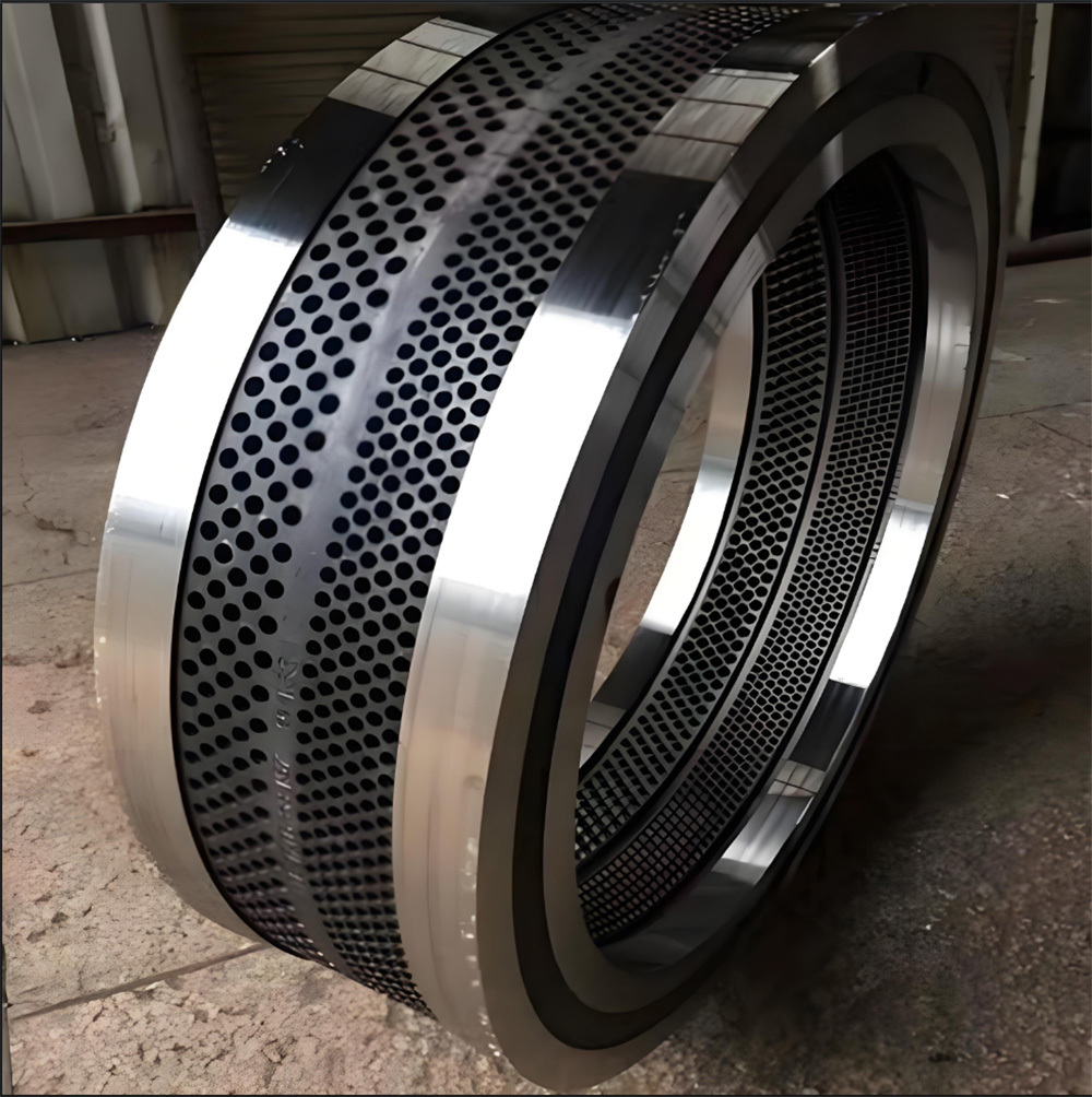
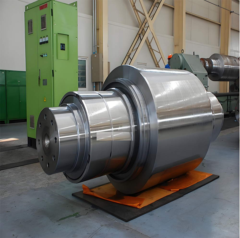
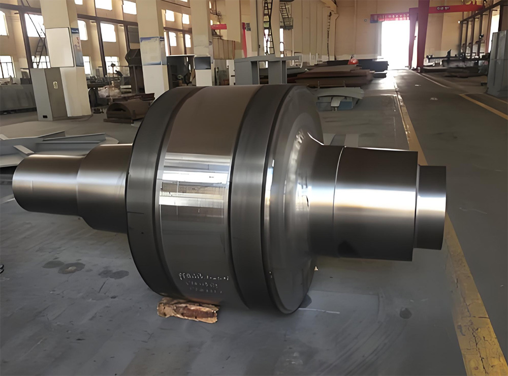
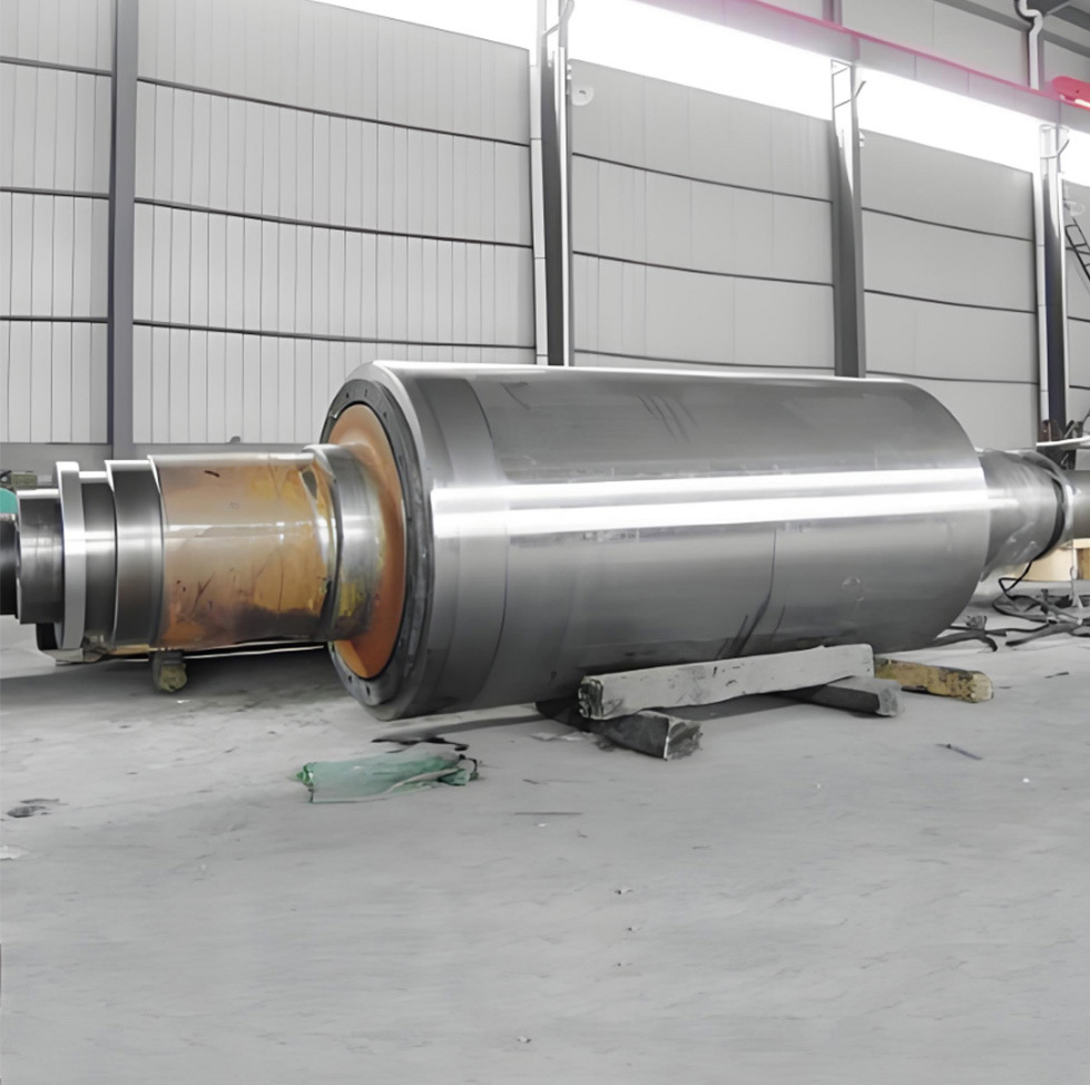
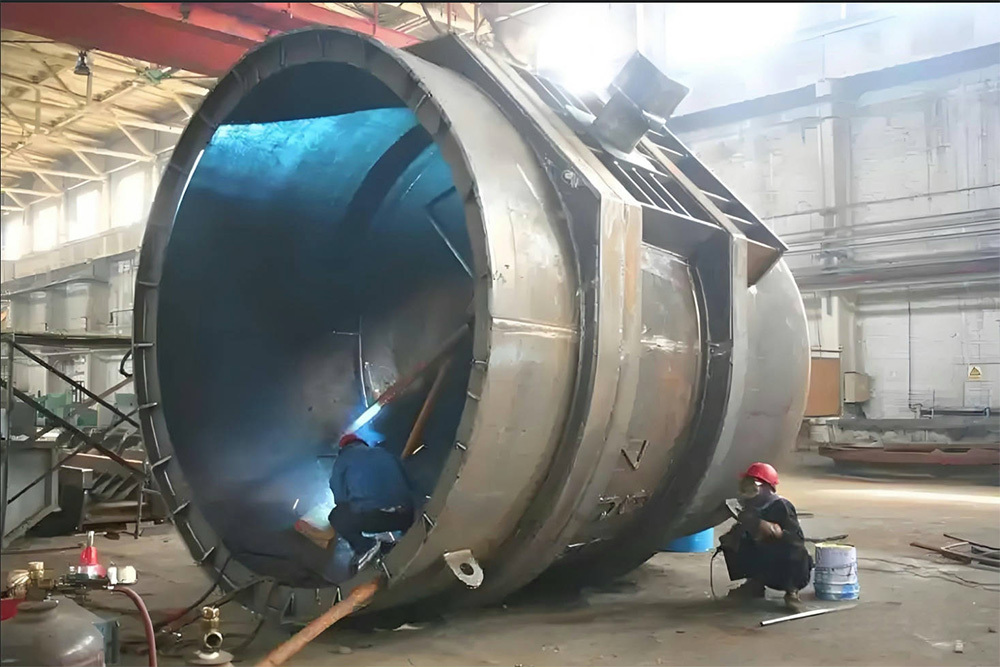
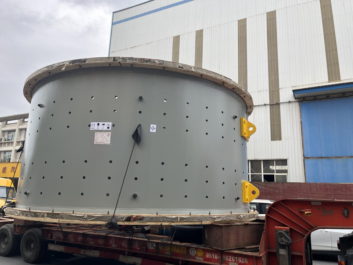
The ball mill cylinder is its core load-bearing component, fabricated by rolling and welding high-strength steel plates. It is lined internally with wear-resistant liners, which withstand the impact and abrasion caused by the steel balls and materials during rotation—making it a critical structure for achieving material crushing.
Core function: Containing the grinding media (steel balls/steel segments) and the material to be ground, withstanding rotational torque (ranging from thousands to tens of thousands of newton-meters) and impact loads, while transmitting motor power to complete the grinding process.
II. Material Selection (Wear-Resistant)
Component |
Recommended Materials |
Standard |
Performance Requirements |
Cylinder shell steel plate |
Q345R/Q355GJC |
GB/T 713 / GB 1591 |
Low-alloy high-strength steel, impact energy ≥34 J at -20°C |
Flange End Cap |
ZG270-500/ZG20SiMn |
GB/T 11352 |
Cast steel parts, UTS ≥ 500 MPa |
Lining plate |
High-manganese steel ZGMn13Cr2 |
GB/T 5680 |
Wear-resistant and impact-resistant (HB ≤ 300) |
Bolt |
35CrMoA/42CrMo |
GB/T 3077 |
High strength (UTS ≥ 980 MPa) |
III. Welding Methods
Weld Type |
Craftsmanship |
Parameter Example |
Cylinder longitudinal seam |
Submerged Arc Welding (SAW) |
Welding wire H10Mn2, current 650–750A |
Cylinder Shell Circumferential Seam |
Twin SAW Welding |
Double wire spacing is 30 mm, with a speed of 40 cm/min. |
Flange-to-cylinder weld joint |
Flux-Cored Arc Welding (FCAW) |
80% Ar + 20% CO₂, heat input ≤ 35 kJ/cm |
Key Processes in Welding Technology
Pre-weld preparation: Material cutting, forming, and beveling (with precision control).
Strict cleaning: Remove oil, rust, water, oxide scale, and other contaminants from the bevel and surrounding areas on both sides.
Assembly tack welding: Use the same welding materials and processes as for the final welds to ensure high-quality tack welds of appropriate length and spacing. Also, inspect assembly gaps and misalignment.
Preheating (if required): Heat evenly to the specified temperature, and monitor and record accordingly.
Welding process:
Weld strictly according to the WPS and welding sequence.
Control interlayer temperature (monitor and record).
When performing multi-pass, multi-layer welding, carefully clean away interlayer slag and spatter. Ensure proper fusion of each weld pass to prevent defects.
Monitor key parameters (current, voltage, speed, gas flow rate, etc.).
IV. Critical Process Control
Bevel Design: Cylindrical Shell Longitudinal Seam: X-Type Bevel (60° Angle, 6mm Root Face)
Cylinder shell circumferential weld: K-groove (outer bevel angle 55°, inner bevel angle 45°)
Deformation prevention measures: After rolling, spot-weld reinforcing rings (to maintain roundness deviation within ≤0.1% of diameter)
Ring seam welding uses a roller stand combined with an anti-creep device, with a rotation speed of 0.5 to 1.5 r/min.
Post-weld treatment: Vibration Stress Relief (VSR): Residual Stress Reduction (as an alternative to thermal stress relief)
Localized Annealing: Stress Relief Treatment at 600°C in the Flange Weld Zone
Welding Process |
Application Scenarios |
Material preparation process |
Flame cutting (CNC cutting), plasma cutting, laser cutting, shearing, and sawing. High-precision bevel machining (such as edge milling and bevel cutting machines). |
Forming process adopted |
Rolling (cylindrical and conical shapes), bending (using a bending machine), pressure forming (with large-scale presses), and roll forming. |
Assembly and Alignment |
Using large-scale tooling fixtures and platforms—such as welding positioners and roller stands—ensures the precise positioning and dimensions of each component. This is a critical step in quality control. |
Common Welding Methods |
Application Scenarios |
Submerged Arc Welding |
Suitable for long straight welds and circumferential seams (such as longitudinal and circumferential seams of cylindrical shells). |
Gas-shielded welding |
MAG (CO2 or mixed gas), MIG (inert gas). Widely used and highly versatile (manual, semi-automatic, automatic), suitable for various positions and joint types. |
Shielded Metal Arc Welding |
Suitable for positions that are difficult to automate, short welds, and repair welding. It is less efficient and relies heavily on the welder's skill. |
Electroslag Welding |
Vertical welding for extra-thick plates (such as box girder diaphragms). |
Narrow-Gap Welding |
Designed for butt joints of ultra-thick plates, it offers high efficiency with minimal deformation. |
Post-weld treatment |
|
Stress |
Large components generally require post-weld heat treatment—either overall or localized (typically stress relief annealing)—to remove weld slag and spatter, followed by grinding of the weld seam and its surrounding areas. This process helps relieve residual welding stresses, preventing deformation, cracking, and improving the material's toughness. |
Orthopedic |
Flame straightening, mechanical straightening (using a press), to control welding deformation. |
Mechanical Processing |
Perform precision machining operations such as milling, boring, and drilling on critical mating surfaces and hole locations. |
We will conduct non-destructive testing, inspection, and testing on the products:
| Project | Content |
| Visual Inspection | Surface defects (cracks, undercut appearance inspection (VT), porosity, arc craters, etc.). |
Ultrasonic Testing (UT) |
Detecting internal defects (such as lack of fusion, incomplete penetration, slag inclusions, cracks, etc.) is especially critical for thick plates. |
Radiographic Testing (RT) |
Intuitively displays internal defects and is commonly used for critical butt joints. |
Magnetic Particle Testing (MT) |
Detection of Surface and Near-Surface Defects (Ferromagnetic Materials) |
Penetrant Testing (PT) |
Detecting surface opening defects (non-magnetic materials). |
Destructive Testing (Sampling) |
Such as tensile testing, bending tests, impact tests, hardness tests, and metallography (typically conducted during process qualification or random inspections). |
Dimensional Inspection |
Check whether the overall structural dimensions and key component dimensions meet the drawing requirements. |
Pressure/Leak Test (if required) |
Such as hydraulic tests, pneumatic tests, and air-tightness tests. |
V. Specification Range
1. Reference to the self-weight of the cylinder
Specifications (Diameter × Length) |
Cylinder wall thickness |
Self-weight range |
Reference overall machine weight |
Φ2.2 × 7m |
22~26mm |
10-12t |
45–55 tons |
Φ3.6 × 6m |
36~40mm |
22–30 tons |
110–130 tons |
Φ4.5 × 12m |
46~50mm |
66–70 tons |
280–320 tons |
Φ5.5 × 8.5m |
58~60mm |
70–80 tons |
450–500 tons |
2. Weight Composition Ratio
Component |
Proportion |
Explanation |
Cylinder shell steel plate |
85% to 90% |
Dominant weight (density 7.85 t/m³) |
Flange End Cap |
8% to 12% |
Cast steel parts (density 7.8 t/m³) |
Lining Plate Bolt |
2%~3% |
High-strength bolt array (over 1,000 bolts per unit) |
Keywords
Previous: Large Riveted and Welded Components


Ball Mill Cylinder
Contact Information
Product Categories
Related Products
Related Products
Ball mill
Ball mill
Rod Mill
(Semi) Autogenous Mill
Mining Hoisting
Single-rope Winding Mine Hoist
Multi-rope friction mine hoist
Well Drilling Hoist
Supporting Equipment
Mining Washing and Selection
Selective Crusher
Centrifuge
-
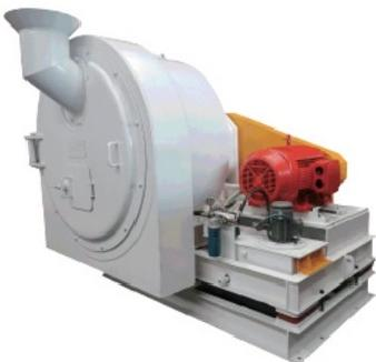
WLL Series Coal Slime Scraper Discharge Centrifugal Dehydrator
-
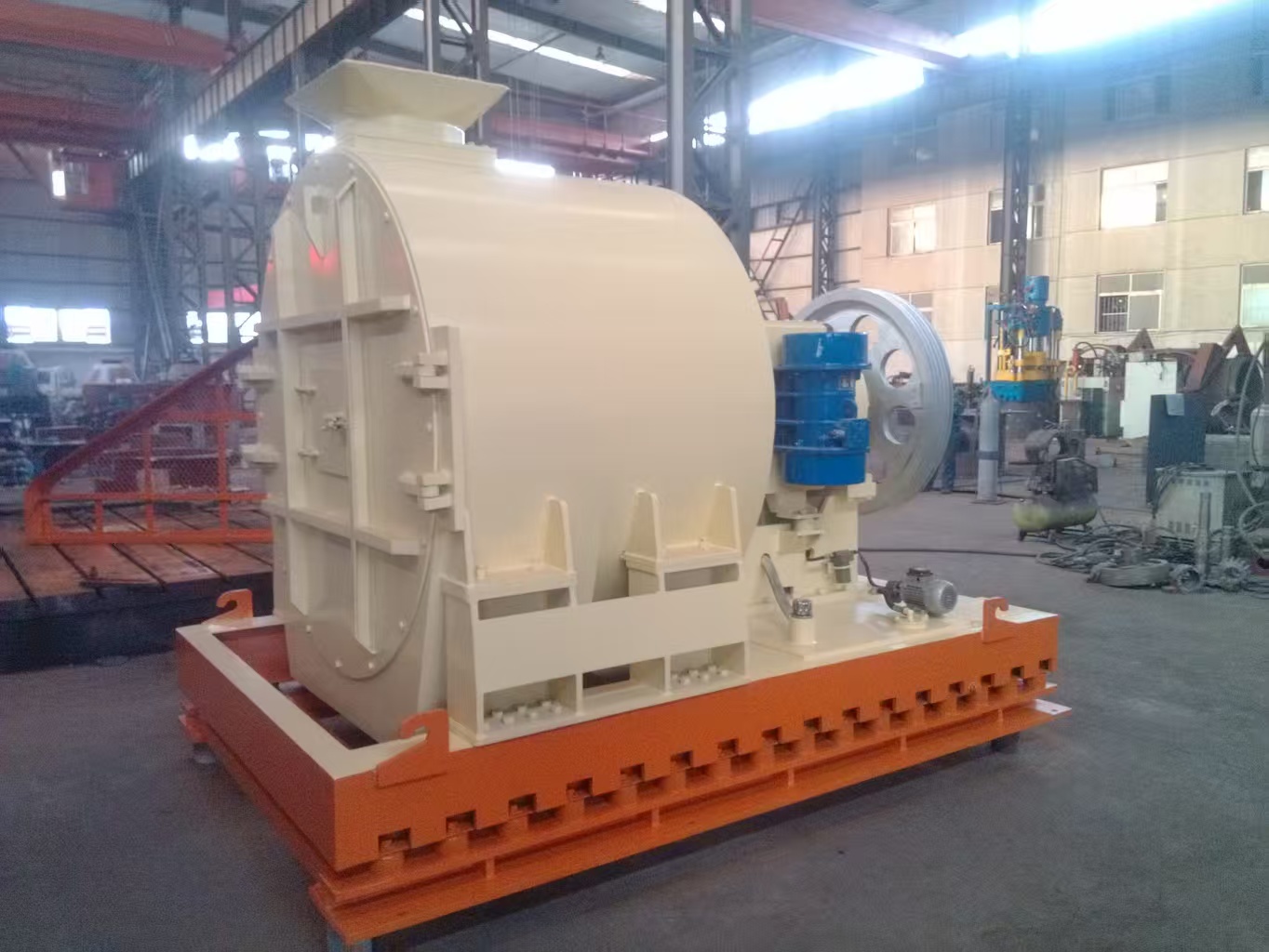
WZY Series Dual-Mass Horizontal Vibrating Centrifugal Dehydrator
-
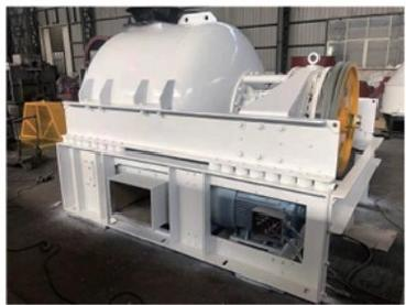
WZL Series Horizontal Vibrating Centrifugal Dehydrator
-
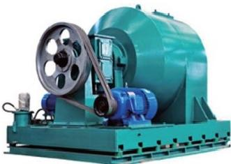
TWZ Series Horizontal Vibrating Centrifugal Dehydrator
-
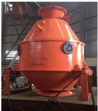
LLS-900 Sludge Centrifugal Dehydrator
-
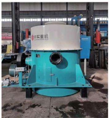
ML Series Coal Slurry Centrifugal Dewatering Machine
-
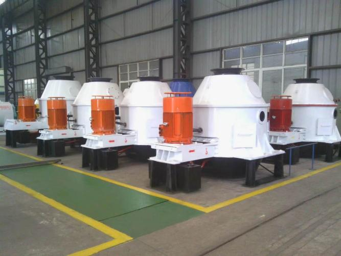
LL Series Vertical Centrifugal Dehydrator
Flotation machine
Filter machine
Grading Machine
Mining Auxiliary Equipment
Gear Reducer Series
-
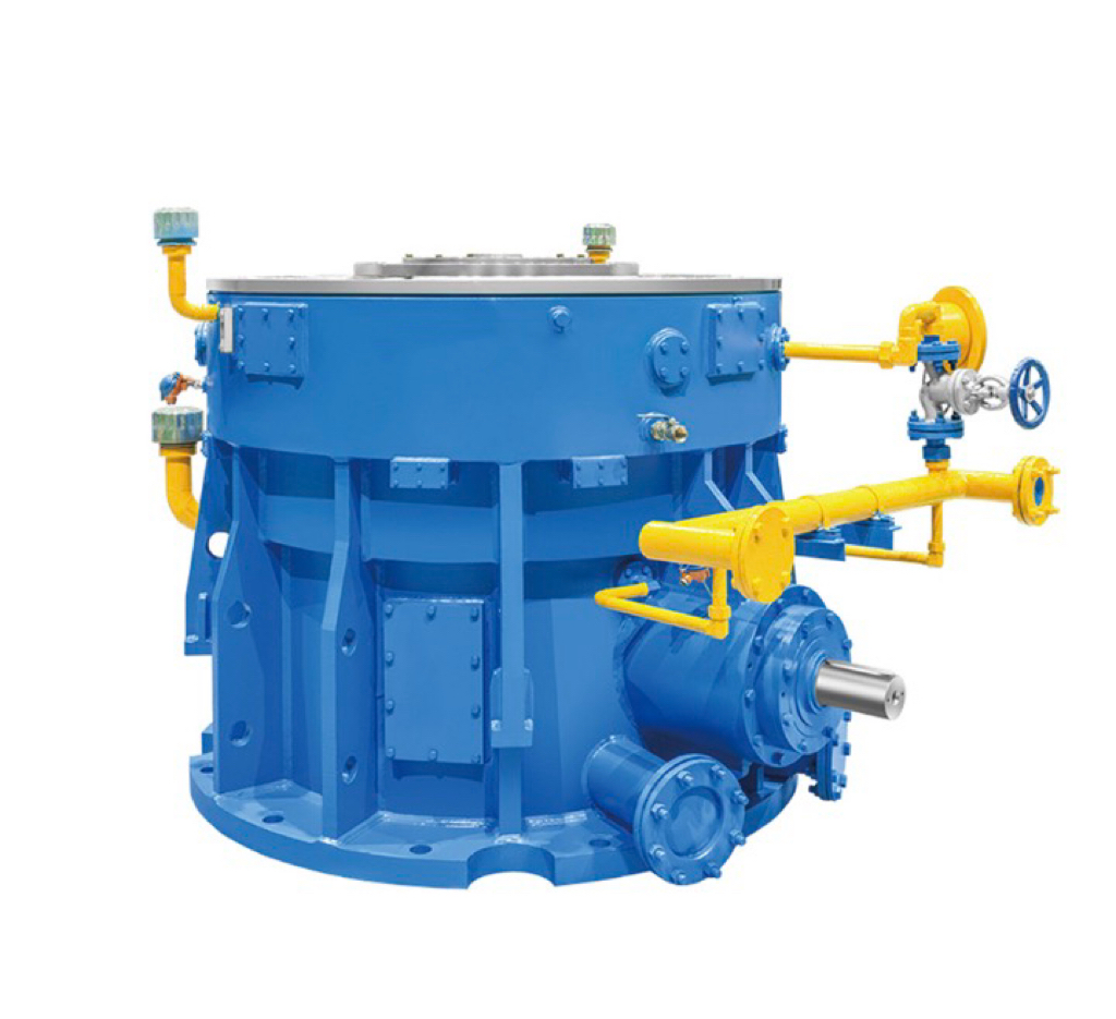
Vertical mill gearbox
-
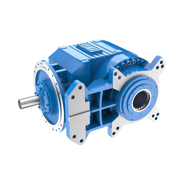
Special reducer for scraper machine
-
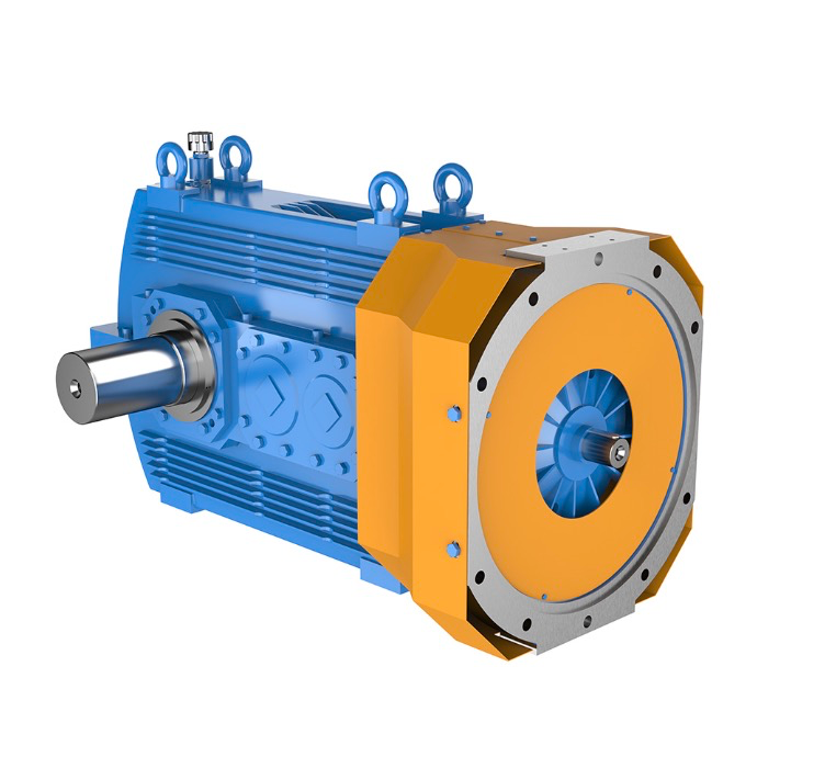
Industry-specific gear reducer
-
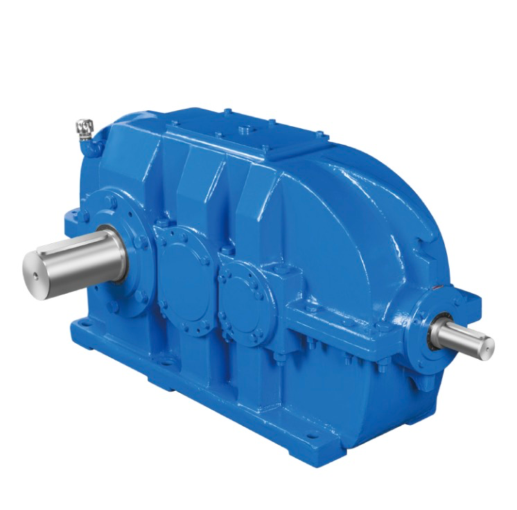
Bevel Gear Reducer
-

Cylindrical Gear Reducer
-
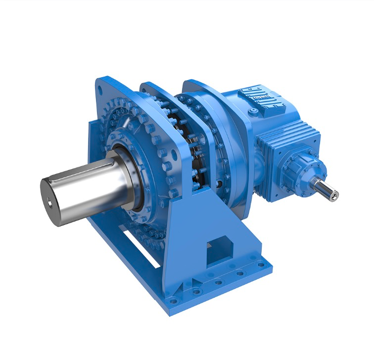
Planetary Gear Reducer
-
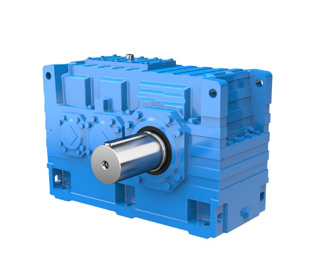
Parallel shaft reducer
-
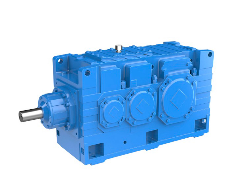
Industrial General Gearbox Series
-
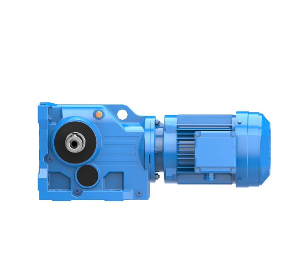
Helical Gear - Bevel Gear Reduction Motor
-
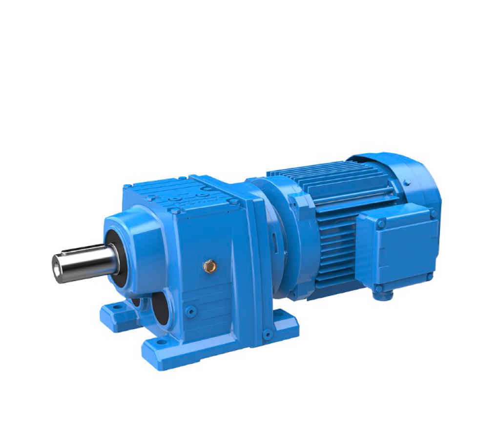
Helical Gear Reduction Motor
-
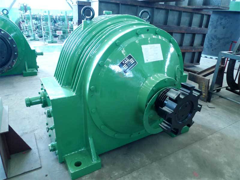
Planetary Gear Reducer
-
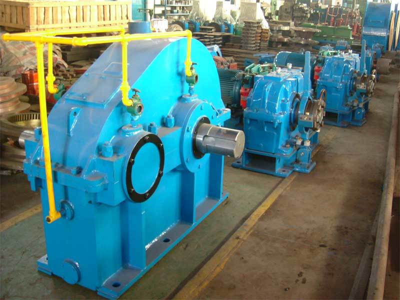
Cylindrical Gear Reducer
Category One
Category Two
Crusher Series
Rotary Crusher
Jaw Crusher
Impact Crusher
Cone Crusher
Ball Press Machine
High-pressure briquetting machine
Medium and High Pressure Briquetting Machine
Rotary kiln
-
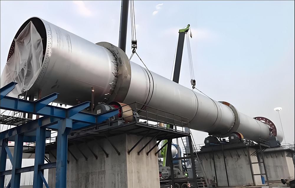
Cement kiln (rotary kiln)
-
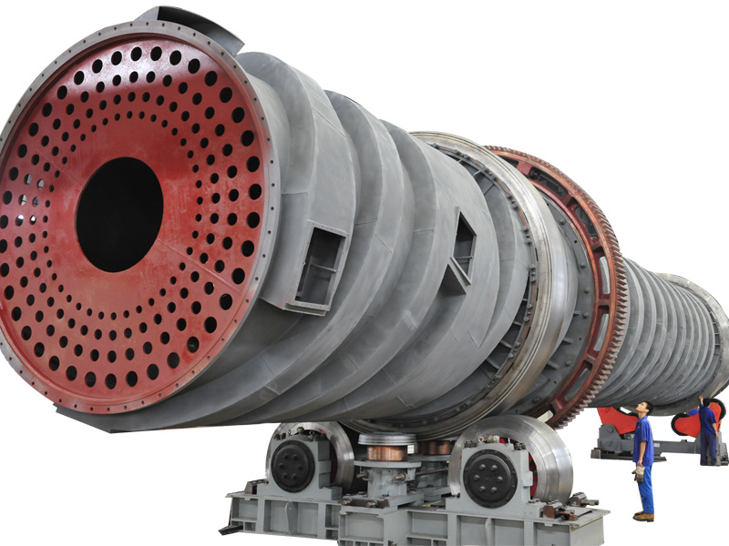
Light gray kiln (self-alkali steam calcination kiln)
-
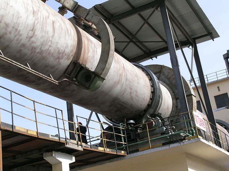
Chemical kiln
-

Oxidation Cooling Kiln
-
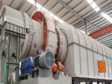
Oxidative roasting rotary kiln (oxidation kiln)
-
Lithium Carbonate Rotary Kiln
-
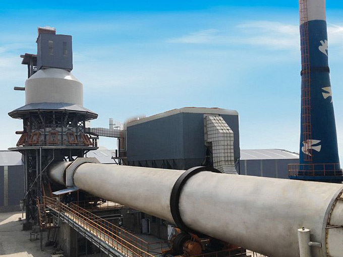
Lime Rotary Kiln
-
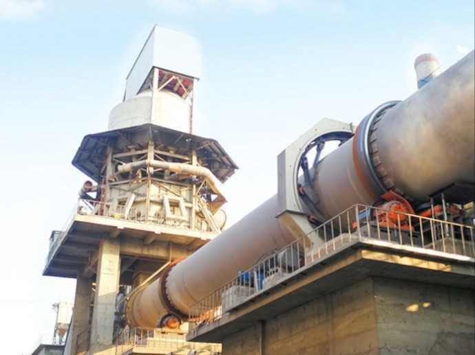
Metal Magnesium Rotary Kiln
-

Architectural Lightweight Aggregate Rotary Kiln
-
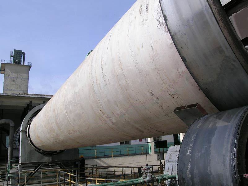
Cement Rotary Kiln
Cast and forged parts
Large castings
Large Forgings
Transmission Accessories
Gear Coupling
Gear
Electro-hydraulic control system
Automation Control
-

GPRS Remote Expert Diagnostic System
-
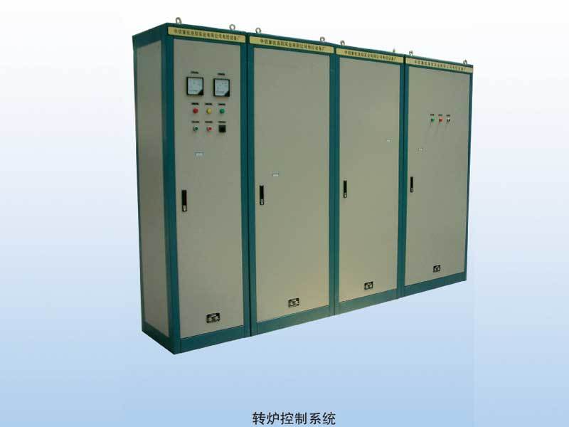
Metallurgical Electrical Control Equipment
-
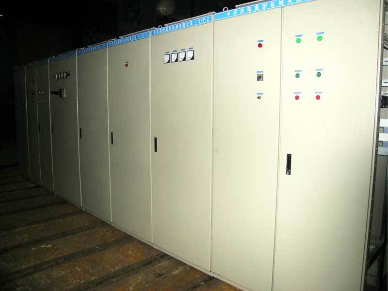
Automated Control System for Mineral Processing and Coal Washing
-
Local System Upgrade
-
Doubly-Fed Variable-Frequency Electric Control System
-
Fully digital DC control system
-
Fully digital low-voltage variable frequency feedback
-
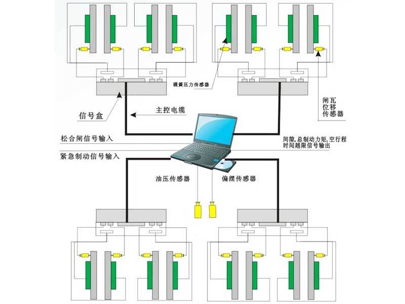
Disc Brake Online Inspection System
-
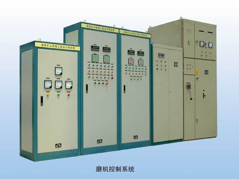
Rotary Kiln Control System
Hydraulic System
-
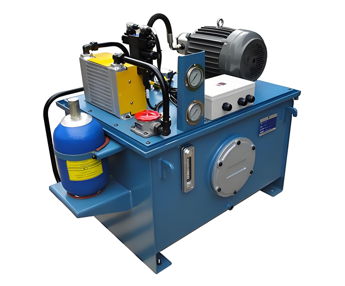
Hydraulic System
-
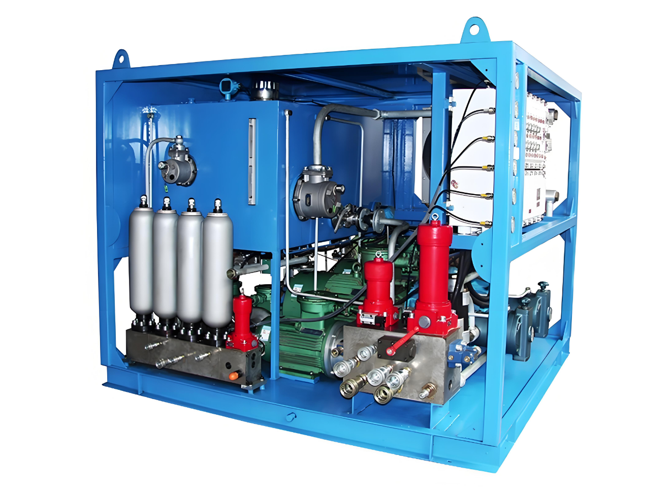
Hydraulic System
-
Hydraulic System
-
Hydraulic System
-
Hydraulic System
-

Hydraulic system
-
Hydraulic system
-
Hydraulic System
-
Hydraulic System
-

Hydraulic Station
-
Variable-frequency servo hydraulic system
-

E119A/E119S, E118A/E118S Explosion-Proof Secondary Brake Hydraulic Station
-
Constant-Deceleration Electro-Hydraulic Braking Control System
-
TE160/TE161/TE162/TE163 Insert-Mounted Control Dual-Stage Braking Hydraulic Station
Hydraulic cylinder
Other accessories
Large welded components
-
Large kiln body riveted and welded components
-
Large furnace riveted and welded components
-
Large Riveted and Welded Components
-
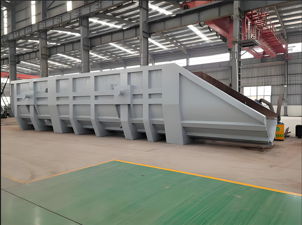
Large Riveted and Welded Components
-
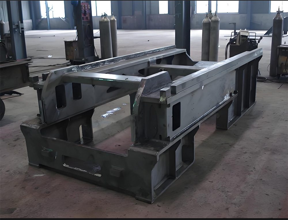
Large Riveted and Welded Components
-
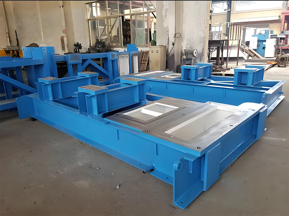
Large steel ladle riveted and welded components
-
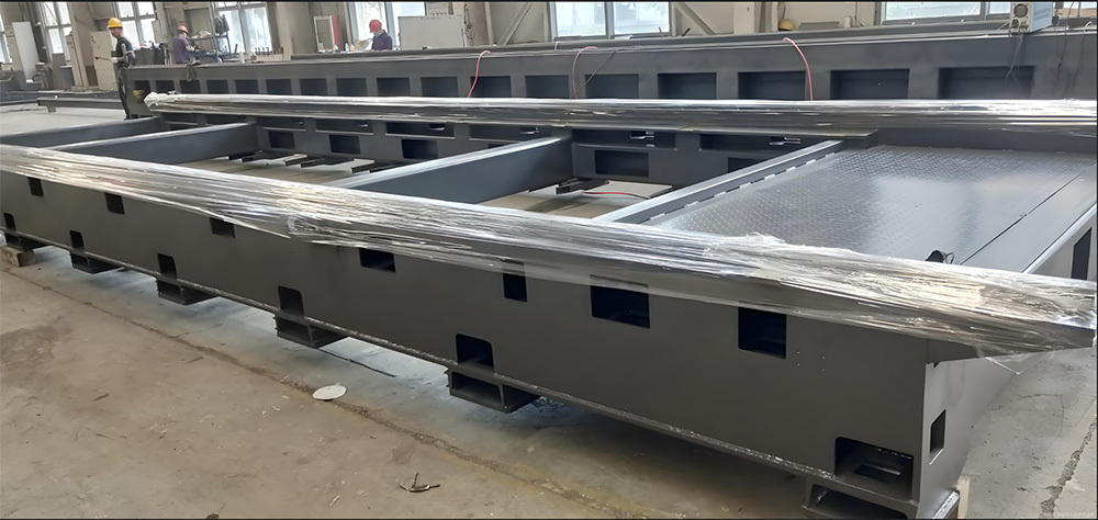
Large base
-
Large Riveted and Welded Components
-
Ball Mill Cylinder
Wear-resistant products
-
Eccentric Crusher Jaw Plate
-
New-Type High-Pressure Roller Wear-Resistant Surfacing Welding Technology
-
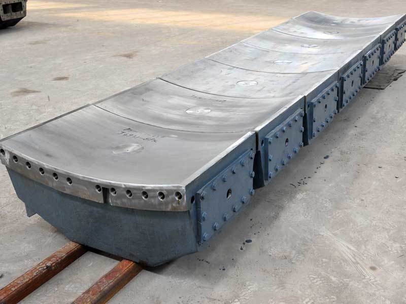
Bus Alloy Bushings
-
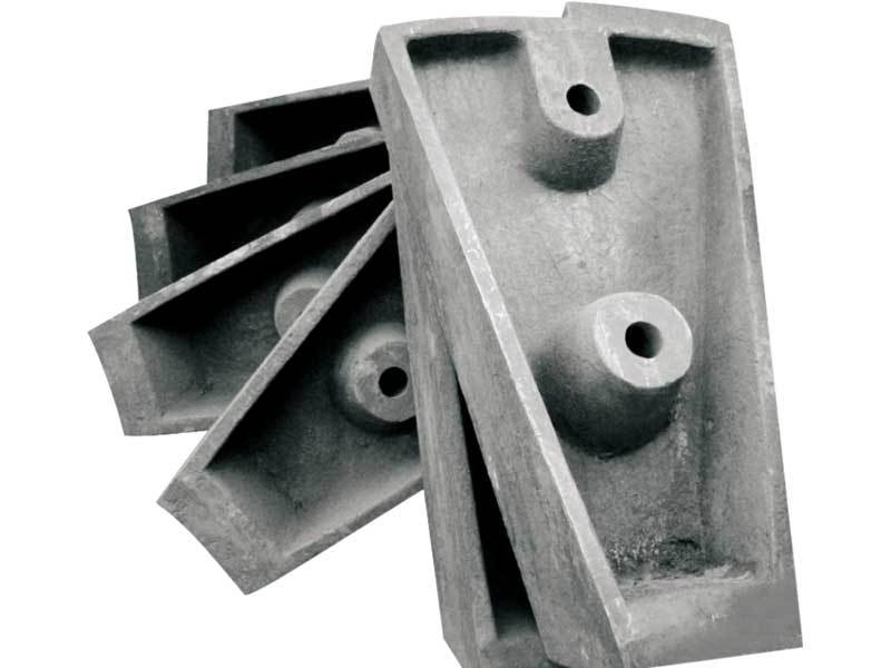
Large ball mill ZGMN13CR2 lining plate
-
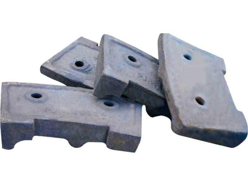
Medium-chromium alloy liner plate
-
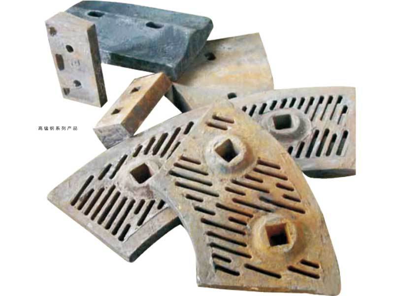
High-manganese steel product series
-

High-precision cast iron parts
-
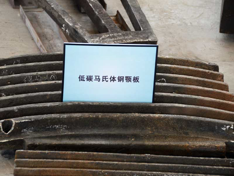
Low-carbon martensitic steel jaw plate
-
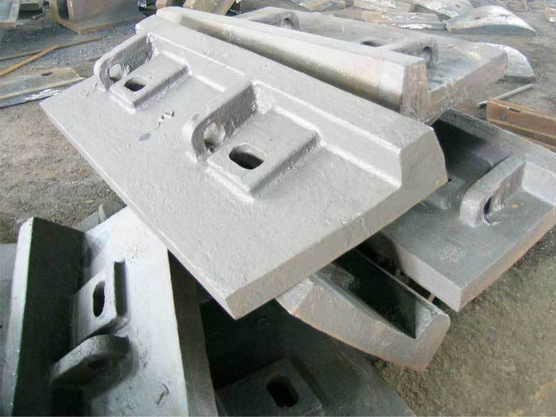
Large Self-Grinding Mill Cylinder Lining Plates
Engineering Plastics
-
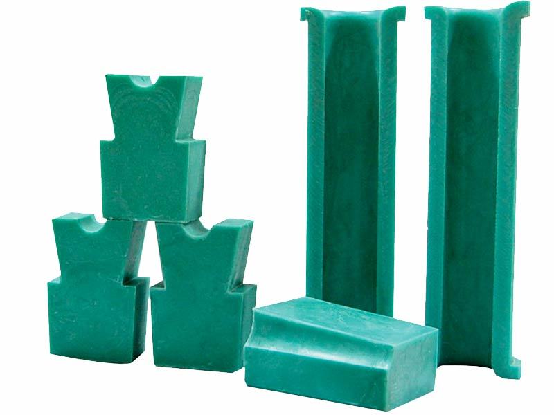
Modified PP sheave and guide wheel lining blocks for elevators
-
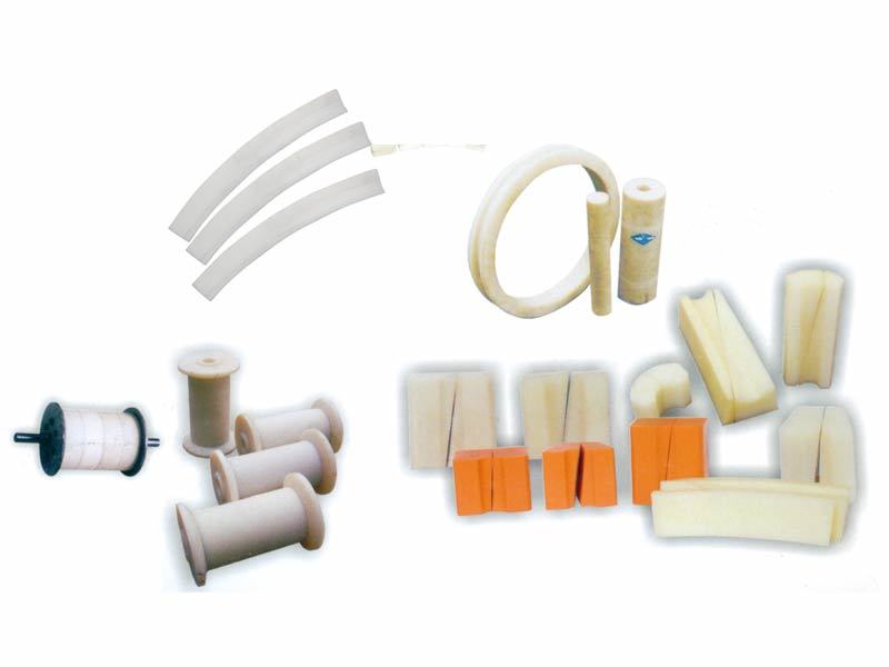
Nylon products
-
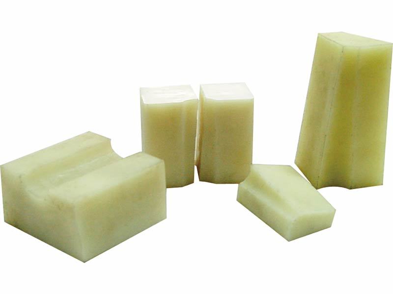
Polyurethane Products
-
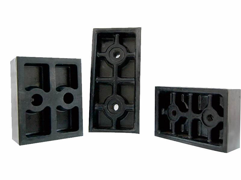
Multi-rope hoist phenolic press blocks, fixing blocks
-
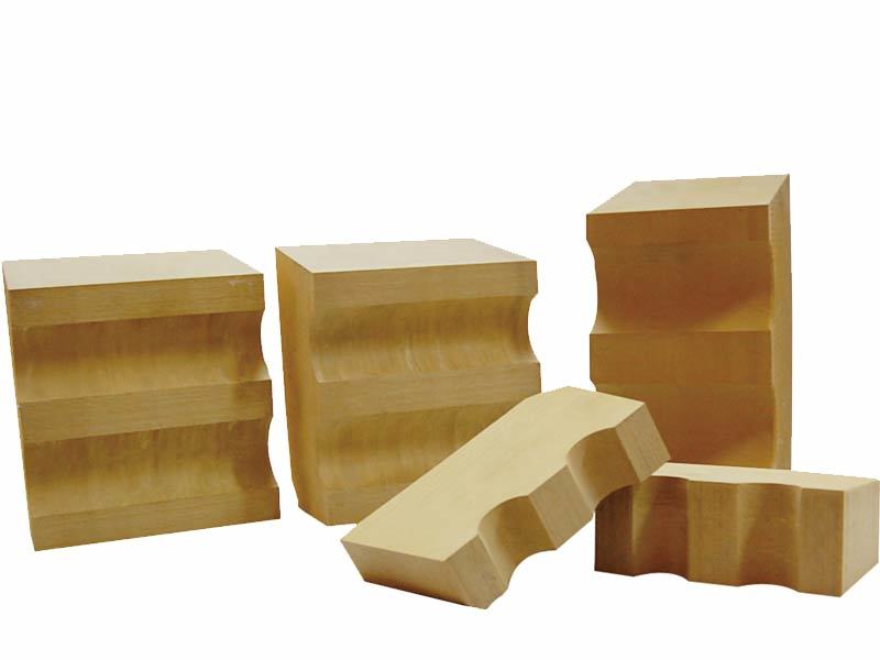
Germany-imported — LUWIPLAST GELB848 Friction Pads
-
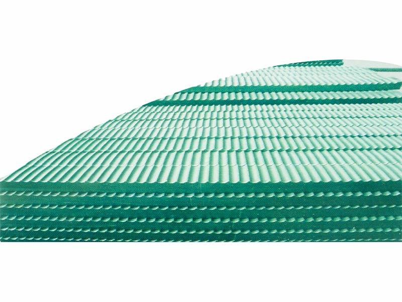
Single-rope mine hoist plastic lining板
-
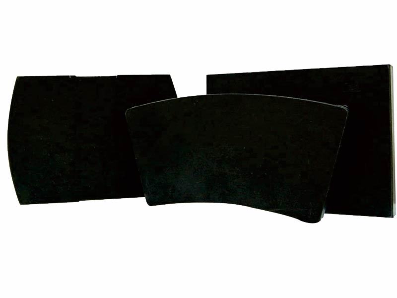
WSM-3 New Eco-Friendly, Non-Asbestos Brake Blocks (Elevator Braking System)
-
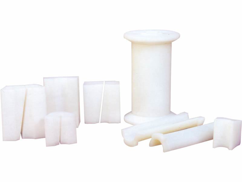
KP-09 Ultra-High Molecular Wheel Sheave Lining Pads
-
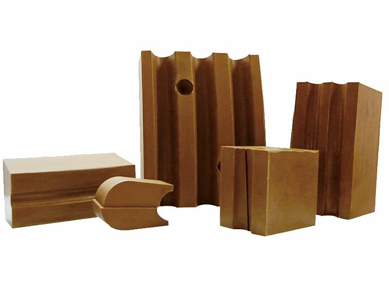
GDM326 Imported Material High-Performance Friction Pads
Roller shaft
crane sheave
Contact Us
No.99 Hengshan Road, Jianxi District, Luoyang City, Henan Province

sweep
CITICTLC
Learn more about dynamic information

